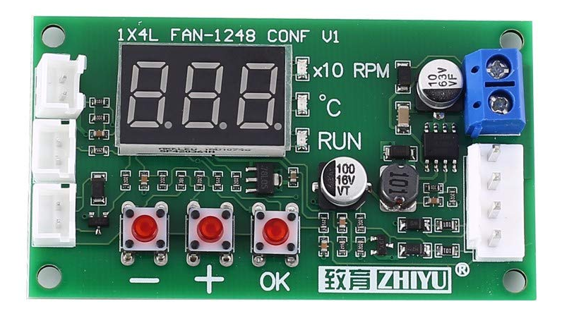
The 1x4l fan-1248 conf v1 pwm fan controller is a capable board for a diy home rack cooling solution.
It is a cheap little device that will fit anywhere inside any enclosure and it can be easily used with standard PC fans after a small tweak.
The big downside of it is that there is no instructions available…
So here we go: here’s the 1X4L pwm fan controller manual!
1. Description
The 1x4l fan-1248 conf v1 is a PWM 4-Wire Fan temperature controller.
It can be used for industrial fans, and with a small tweak, it can be used for standard 4-wire PWM PC fans like Noctua, Corsair, Cooler Master, Thermaltake, NZXT, etc.
2. Features
- Digital LED display
- Supports EC four-wire fan control
- Supports low-temperature fan shutdown
- Wide voltage operation
- Supports anti-sequence fan
- Supports EBM four-wire fan
3. Parameters
- Product Name: Zhiyu 1X4L an-1248 conf v1 PWM 4-Wire Fan Temperature Controller
- Working Voltage: DC 11V ~ 55V
- Working Current: 0.1A (MAX)
- Fan Current: 5A (MAX)
- PWM Range: 5% ~ 100% or 0%
- PWM Frequency: 20KHz / 2.5KHz
- PWM Signal Amplitude: 10.5V (no load)
- Temperature Measurement Range: -9.9℃ ~ 99.9℃
- Working Temperature: -25℃ ~ 85℃
- Working Humidity: 5% ~ 95% RH
- Sensor Wire Length: 1 meter
- Size: 70.5 x 40.5 x 13.5mm
5. Package contents:
- 1 piece PWM 4 wire fan temperature regulator
- 1 x NTC temperature sensor
The power supply is not included!
This one on Amazon is good candidate: https://amzn.to/3eGcWvd
6. Notes
- This product is mainly designed for industrial fans.
- The user interface is different from conventional PWM fan controllers. The direct shutdown feature only supports PWM fans with a signal shutdown function (fan stops after the PWM speed control line is grounded).
- If additional fans need to be shut down at same time as the primary PWM fan, they can be controlled to cut off power through the external relay trigger circuit, supplied by the ‘relay’ header on the PWM controller’s PCB.
7. Interface Introduction
- Power interface:
The main power input interface (11v ~ 55v): + | – | Supplies the main power to the control board PCB, also providing the power to pass through to the fan output interface. - Fan interface:
Fan output interface (4-pin): Fan + | Fan – | Temp Sense | PWM output. This is a JST VH 3.96 connector. Standard PWM 4-Wire PC fans have a Molex connector. - Temperature probe interface (2-pin):
Connect NTC probe parameter 10K B=3950. - Alarm signal port (2-pin):
High-level output during normal operation, low-level output when the fan is abnormal. - Relay interface (2-pin):
Expansion interface. Drives a 9V or 12V relay, which can be used to control an addtional fans power circuit, when the fan control stops (the ‘RUN’ LED indicator turns off), the relay opens.
8. Button Description
- 1. + and – Buttons: Short-press buttons to switch the display mode, + or – is also used to increase or decrease a value during parameter setting (long-press to increase or decrease a parameter quickly).
- 2. OK Button:
- 2.1 With the PCB powered ON, short-press the OK button to enter the inherent PWM output setting, the range is 5% ~ 100%, short-press again to save and exit.
- 2.2 With the PCB powered ON, long-press ‘OK’ button to enter the temperature parameter setting. After entering, modify the first parameter (L__) by pressing the + Button and – Button. When the ‘L’ setting is as desired (e.g. L35), short-press the ‘OK’ Button to save and move to the next parameter adjustment (H__), modify by pressing the + Button and – Button. When the ‘H’ setting is as desired (e.g. H45), short-press the OK Button to save and move to the next parameter adjustment (C__), modify by pressing the + Button and – Button. When the ‘C’ setting is as desired (e.g. C25), short-press the OK Button to exit the temperature parameter adjustment mode.
- L = Acceleration Temperature
- H = Full Speed Temperature
- C = Turn-off Temperature
- 2.3 With the PCB powered OFF, hold down the ‘OK’ Button, turn ON power (while holding down ‘OK’ button) until it enters the function setting (F__), modify parameters with the + and – Buttons, short-press the ‘OK’ button to move to the next parameter, you can set the PWM output frequency 20KHz / 2.5KH (the display will show “F20 / F2.5”) in turn. PWM output direction forward/reverse (the display show “P1 / P-1”, short-press the ‘OK’ Button again to save and exit.
9. Explanation of Temperature Parameters
- Acceleration Temperature (the display showing “L**”, “*” stands for the number): the range is 5℃ ~ 94℃.
When the temperature rises and exceeds this temperature, the PWM output starts to increase as the temperature rises. - Full Speed Temperature (the display showing “H**”): The range is 10℃ ~ 99℃ .
When the temperature rises or exceeds this temperature, the PWM always outputs 100% and the fan runs at full speed. - Shut-down temperature (the display showing “C**”): Low-temperature shutdown temperature.
The range is 0℃ ~ 92℃. When this value is set to > 0, the low-temperature shutdown function is enabled.
When the temperature is lower than this temperature, the output is turned off (PWM signal and extended relay output are turned off at the same time).
When the temperature rises above the acceleration temperature in the off state, the fan restarts and changes speed with the temperature, if the shutdown temperature is set to 0, the low temperature shutdown function is disabled, and the PWM and extended relay output interfaces will always output. - The difference between the acceleration temperature and the full speed temperature must not be lower than 5℃, and the difference between the closing temperature and the acceleration temperature must not be lower than 2℃.
If the value will break the above temperature difference when modifying the parameters, the program will automatically adjust the other two parameters.
10. Show Description
- “X10 RPM”
Speed unit displaying.
When this light is on, the display is currently indicating the fan speed, which is the value after the speed divided by 10.
For example, if the display indicating is 256, the actual fan speed is 2560 RPM (revolutions per minute). - “℃”
Temperature unit displaying.
When this light is on, the display is currently indicating the temperature measured by the current probe. - “RUN”
Fan running indicator.
This light illuminates when the fan is running, and goes out when the fan is off.
Note that this is the control status, not the actual fan condition.
If the fan fails, the alarm signal port outputs a low level during operation (when the RUN light is on).


Thanks for the great guide!
Cheers Henk,
Happy to hear this was useful!
Hello, bought one of these. Thanks for your valuable instructions! One question: do you know how to reduce the display brightness (maybe by replacing a resistor)? Or maybe insert a switch in a trace to be able to switch on/off the display only, leaving the controller operational?
Thanks in advance!
Hi Hugo,
Thanks for the comment.
I must admint I have no clue how to achieve this except the good ol’ tape and marker! 🙂
Cheers mate
Hi, please can you advise hiw to hook up standard 4pin pwn pc fan to this board?
Thanks
V
Hi Vladimir,

Yes sure I had the same problem…
You need to swap the connector with a JST VH 3.96mm 4 pin.
I ordered them on Aliexpress here: https://a.aliexpress.com/_mq4dLpu
I think a pair of cables has to be inverted in order for the fan to spin properly.
The indication on the board may be inaccurate…
Here’s a picture of the board in my home rack connected to a pair of Noctua fans.
Fantastic guide, thank you so much for fighting it up!
I’ve now got one, but I’m finding that the cutoff temperature isn’t working? I.e I set “C_” to 40 degrees but the fan keeps spinning. Am I missing something?
For my setup, I’ve spliced a pc molex pwm cable on to a connector, switching the positive and negative. Im using a “be quiet” pwm fan. Set the “L_” to 45, “H_” to 60 and “C_” to 40. Then “F” to 2.5 and “P” to 1.
Have you tried using this controller with multiple fans? Using it only for speed control, power comes from another source. I note that it works OK w/ 2, but once you add more than 3, it starts “clipping”.
Hi, Thanks for this, Do you know if a schematic of the board exist?
I am confused on the output current, I want to drive a 24V, 61W (so 2.5A output min is needed).
I checked the XL7005A (TSSOP 8 located close to the blue screw terminal connector), and the output current is 0.4A, so there is some additional components on the board.
Hi, with mine every thing seem to work correctly but the fan never turns off. On The board “run”, led goes off when the C temp is reached but the fan keeps running. Can you help?
I’ve figured out something that may be helpful to others. I wanted to control a auto radiator fan by temp, temp increase equals fan speed increase. I used the s output only to the black potentiometer connection on a larger pwm. There is no potentiometer installed on the larger pwm and the other potentiometer wires are capped on large pwm. It works great so far. Any thoughts?
Hello, Thank you for the detailed explanation, however, in my case it is a little different, I am using a fan with 2 pin (positive and negative) can I use this controller board to just switch ON and OFF the Fan motor based on my specified temperature. The fan that I am using does not have a PWM input signal and therefore I cannot control the speed of the motor. Therefore, instead of just controlling the speed of the motor I want to switch it ON and switch it OFF whenever the temperature exceeds or lower the specified temperature respectively. Right now the controller is supplying the power to the fan even when the temperature parameter does not satisfy my set temperature.
Can you please guide me further.